Loading video…
All breakouts
13.5Text-HeavyHow-To hookB2B
Hook
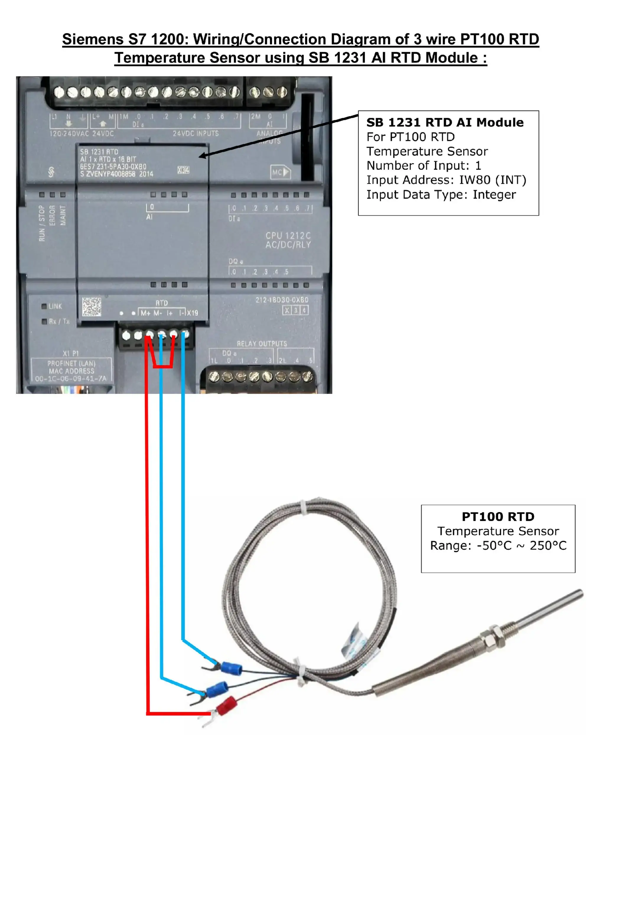
Siemens S7 1200: Wiring/Connection Diagram of 3 wire PT100 RTD Temperature Sensor using SB 1231 AI RTD Module :
@sparksystemes
14.1K followers · usually 1.7K views a post
Views
26.4K
Likes
1.3K
Comments
5
Shares
91
Why it worked
The post provides clear, step-by-step visual guides for connecting industrial sensors to a Siemens S7 1200 PLC and includes sample programs for data processing. This practical, educational content directly addresses common challenges faced by engineers and technicians in industrial automation, making it highly valuable and shareable within that niche.
Summary
This series of images provides wiring and connection diagrams for various sensors and components with the Siemens S7 1200 PLC. It covers PT100 RTD temperature sensors, K-Type thermocouple temperature sensors, PNP inductive proximity sensors, and potentiometers, along with sample programs for reading data in TIA Portal.
Structure
- 1Diagram for PT100 RTD sensor
- 2Diagram for K-Type thermocouple sensor
- 3Sample program for reading sensor data
- 4Diagram for PNP inductive proximity sensor
- 5Sample program for proximity sensor
- 6Diagram for potentiometer
- 7Sample program for potentiometer data
On-screen text
Siemens S7 1200: Wiring/Connection Diagram of 3 wire PT100 RTD Temperature Sensor using SB 1231 AI RTD Module :
SB 1231 RTD AI Module
For PT100 RTD
Temperature Sensor
Number of Input: 1
Input Address: IW80 (INT)
Input Data Type: Integer
PT100 RTD
Temperature Sensor
Range: ~50°C ~ 250°C
Siemens S7 1200: Wiring/Connection Diagram of 2 wire K-Type Thermocouple Temperature Sensor using SB 1231 AI TC Module :
SB 1231 TC AI Module
For K-Type Thermocouple
Temperature Sensor
Number of Input: 1
Input Address: IW80 (INT)
Input Data Type: Integer
K-Type Thermocouple
Temperature Sensor
Range: -200°C ~ 1300°C
Siemens S7 1200: How to read data from PT100 RTD and K-Type Thermocouple Temperature Sensors in TIA Portal (Sample Program) :
CONV
Int to Real
ENO
"Tag_3"
DIV
Auto (Real)
ENO
"Tag_3"
%MD0
%MD0
"Temp Sensor
Input"
IN
OUT
%MD4
"Actual Temp"
IN1
IN2
OUT
Siemens S7 1200: Wiring/Connection Diagram of PNP Inductive Proximity Sensor:
Connect Black Output wire
to PLC input pin
When the proximity switch
is on it sends +24 signal
to the PLC Input
Sinking Connection
1M to
-0 Volt DC
Connect Brown wire to
+24 Volt DC
Connect Blue wire to
-0 Volt DC
Connect 1L to
+24 Volt DC
Connect PLC
Digital output to
Lamp one end
Connect Lamp Other
End (COM) to
-0 Volt DC
Siemens S7 1200: How to read data from
PNP Inductive Proximity Sensor in TIA Portal (Sample Program) :
"Proximity
Sensor Signal"
%Q0.0
"Green Lamp"
CTU
Int
CU
CV
0
"IEC_Counter_
0_DB"
%DB1
R
PV
5
%Q0.0
"Reset Button"
%Q0.1
Siemens S7 1200: Wiring/Connection Diagram of
Potentiometer to PLC Analog Input:
Connect 2M to
Ground
Connect
Potentiometer
Output Pin to
PLC Analog
Input Channel
0 (IW64 Int)
Connect VCC
Pin to
+10 Volt DC
Connect GND
Pin to
-0 Volt DC
Siemens S7 1200: How to read Analog data (0~10 Volt) from
Potentiometer in TIA Portal (Sample Program) :
NORM_X
Int to Real
%WG64
"AI 0"
"VALUE"
0
MIN
27648
MAX
%MD10
"Tag_9"
OUT
SCALE_X
Real to Dint
%MD14
"Tag_10"
VALUE
10
MAX
%MD18
"Analog signal
processed"
OUT
Original caption
#scada #instrumentation_and_control_engineering #industrial #explore #siemens
More from @sparksystemes
More breakout videos from this creator.