Loading video…
All breakouts
5.4Text-HeavyOther hookB2B
Hook
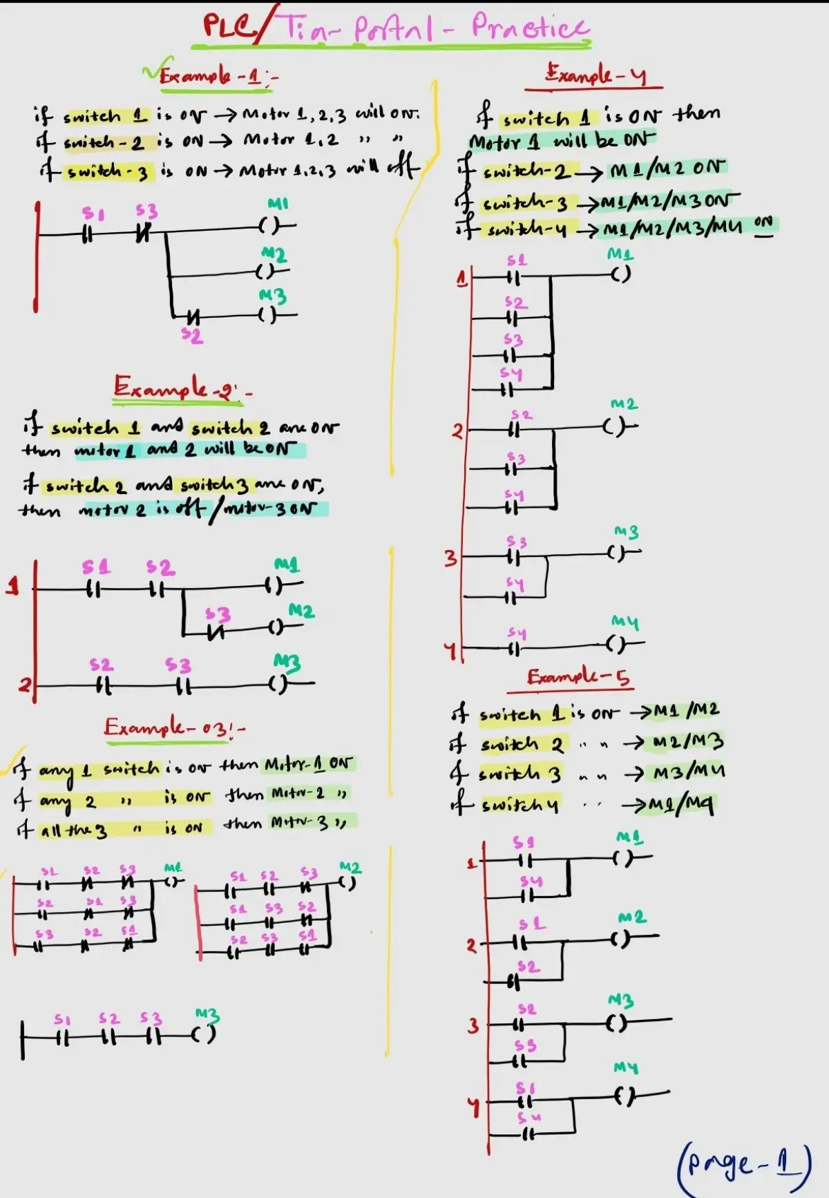
PLC / Tin- Portal - Practice
@sparksystemes
14.1K followers · usually 1.7K views a post
Views
10.1K
Likes
492
Comments
4
Shares
25
Why it worked
This content provides a comprehensive collection of examples and explanations related to PLC programming and logic gates. The clear, step-by-step presentation and the use of visual aids like ladder diagrams and truth tables make complex concepts accessible and easy to understand for students and professionals in the field.
Summary
This is a multi-page document presenting various examples of programmable logic controller (PLC) programming, logic gates, and electrical equivalents. It covers different scenarios and their corresponding ladder logic diagrams and Boolean expressions.
Structure
- 1Introduction to PLC practice examples
- 2Examples of logic circuits and their Boolean expressions
- 3Explanation of logic gates and their equivalents
- 4Further examples of logic circuits and their applications
- 5Push button on/off logic implementation
On-screen text
Example-1
if switch 1 is ON -> Motor 1,2,3 will ON;
if switch-2 is ON -> Motor 1,2
if switch-3 is ON -> Motor 1,2,3 will off
M1
M2
M3
S2
S3
Example-2
if switch 1 and switch 2 are ON
then motor 1 and 2 will be ON.
if switch 2 and switch 3 are ON,
then motor 2 is off/ motor-3 ON
1
S1
S2
S3
M1
M2
M3
Example-03!
if any 1 switch is ON then Motor-1 ON
if any 2 switches is ON then Motor-2 ON
if all the 3 switches is ON then Motor-3 ON
S1
S2
S3
M1
S1
S2
S3
M2
S1
S2
S3
M3
Example-4
if switch 1 is ON then
Motor 1 will be ON
if switch-2 -> M1/M2 ON
if switch-3 -> M1/M2/M3 ON
if switch-4 -> M1/M2/M3/M4 ON
1
S1
S2
S3
S4
M2
2
S1
S2
S3
M3
3
S1
S2
M4
4
S1
Example-5
if switch 1 is ON -> M1/M2
if switch 2 -> M2/M3
if switch 3 -> M3/M4
if switch 4 -> M4/M1
1
S1
M1
2
S2
M2
3
S3
M3
4
S4
M4
(page-1)
Example-6
if switch 1 is ON -> LED-1 ON
if switch 2 -> LED-2ON/
LED-40FF
if switch 3 -> LED-11 ON
if switch 4 -> LED-IV OFF
Note:- Do not turn the switches
off once turned ON.
S1
S2
L1
S3
S4
L2
S1
S2
L3
S3
S4
L4
Example-7
if switch 1 ON -> LED 2/2 ON
if switch 1 OFF -> LED 2/2 will
be still ON
if switch 2 is ON -> LED 0/1 ON
if switch 2 is OFF -> LED 0/1 IV
will be still ON
S1
L2
(S)
L1
(S)
S2
L2
(S)
L1
(S)
S4
L4
(S)
S3
L3
(S)
@here we need (set coil)
to turn ON S
Example-8
if switch 1 is off then ->Motor(1,2,3,4)
if switch 1 is off then still ->Motor(1,2,3,4)
1
MO.0
(switch8)
Tag-0
2
MO.0
Tag-0
3
MO.0
Tag-0
4
MO.0
Tag-0
Example-9
if switch 1 is ON -> motor 1/ motor 2
if switch 1 is off -> motor 1/ motor 2 -> ON
if switch 2 is ON -> motor 3/ motor 4
if switch 2 is off -> motor 4 ON
1
S1
M1
M2
2
S1
M1
M2
3
S2
M3
M4
4
S2
M4
Example-10
if switch 1 is ON -> Motor 1/2 -> ON
if switch 1 is off -> Motor 1/2 -> ON
if switch 2 is ON -> Motor 1/2 -> ON
1
S1
(M1)
(M2)
2
S1
(M1)
(M2)
3
S2
(M1)
(M2)
4
S2
(M1)
(M2)
(page-02)
Example-11
if switch 1 is ON -> M1/M2(ON)
if switch 1 is off -> M1->off
if switch 2 is ON -> M2->off
M3->ON
M4->ON
1
S1
(M1)
(M2)
2
S1
(M1)
(M2)
3
S2
(M3)
(M4)
4
S2
(M3)
(M4)
5
Tag-0
MO.0
Tag-1
M4
Example-12
y1 = A1.B1 + C1 + D1
y2 = A2.B2.C2 + D2
1
A1
C1
B1
D1
A2
C2
B2
D2
(y1)
(y2)
Example-13
y1 = A1.B1
y2 = A2.B2 + C2.D2
1
A1
B1
C2
B2
D2
(y1)
(y2)
Example-14
y1 = (A1+B1) (C1+D1)
y2 = (A2+B2) C2
1
A1
B1
C1
D1
A2
B2
C2
(y1)
(y2)
Example-15
y1 = A1.B1 + A1.B1'
y2 = A2'.B2 + C2.D2
1
A1
B1
A1
B1'
2
A2'
B2
C2
D2
B2
(y1)
(y2)
(page-03)
Example-16
y1 = (A1+B1) C1.D1
y2 = A2.B2.C2' + D2.E2'.F2'
1
A1
B1
C1
D1
2
A2
B2
C2'
D2
E2'
F2'
(y1)
(y2)
Example-17
y = A.B.C + D' + E
1
A
D'
B
C
E
(y)
Example-18
y = [(A'+B')C] + D.E
1
A'
B'
C
D
E
(y)
Example-19
y = A'.B + C.d
1
A'
C
B
d
(y)
Example-20
y = (A.B.C+D) E.F'
1
A
B
C
D
E
F'
(y)
Example-21
An Alarm is ON when
-> Switch 1 is OFF.
-> Switch 2 is ON or
Switch 3 is ON or
both are ON.
-> Switch 4 and 5 - both ON
-> One or more of switch
6,7 OR 8 are ON
S1
S2
S3
S4
S5
S6
S7
S8
Example-22
A
B
C
D
E
F
(y)
(page-04)
Logic Gate Name
Symbol
Electrical Equivalent
Truth Table
BUFFER
NOT
NAND
OR
VEGA DEGIL
(NOR)
OZEL VEYA
(XOR)
Example-23
A
C
D
(y)
Example-24
A
B
C
D
E
F
(y)
Example-25
A
B
C
D
E
F
(y)
push button on/off
-> when Switch 1 (PB) is turned on
(pressed) and turn off (release)
then op will be on.
-> and then, when switch 2 (OB)
is turned ON (Pressed) and
turns off (release) then op/
will be off.
10:0
Start push button
Q.0.0
ON/OFF
Tag-0
1
MO.0
Tag-0
ON/OFF
2
MO.0
Tag-0
ON/OFF
Start.b
IO.1
MO.0
Tag-1
Stop.b
IO.0
Tag-1
(page-05)
Original caption
#LaplaceTransform #TransferFunction #ControlSystems #PLC #MQTT
More from @sparksystemes
More breakout videos from this creator.